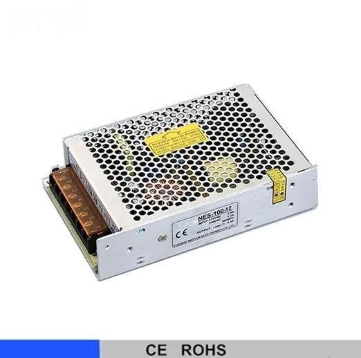
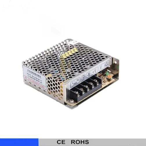
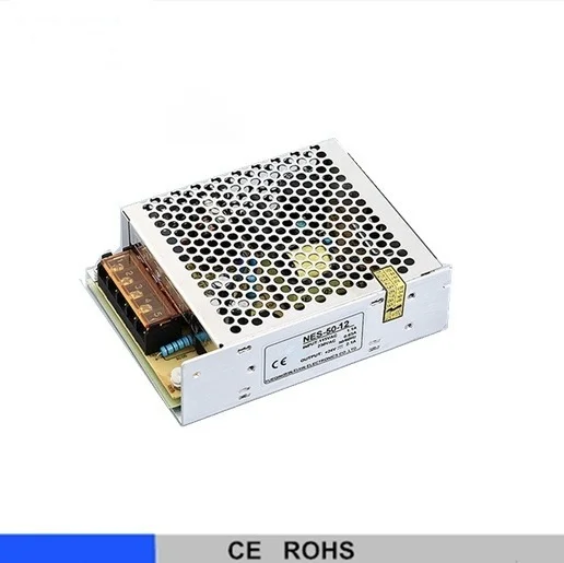
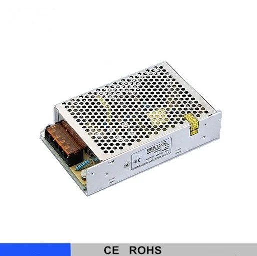
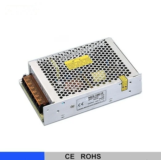
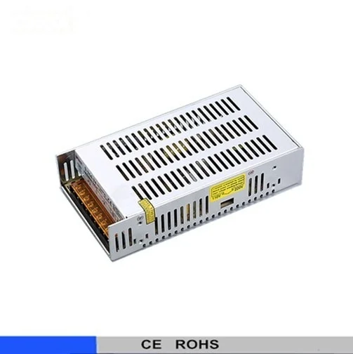
| MODEL | NES-100-5 | NES-100-7.5 | NES-100-9 | N ES-100-12 | NES-100-15 | NES-100-24 | NES-100-48 |
| OUTPUT | DC VOLTAGE | 5V | 7.5V | 9V | 12V | 15V | 24V | 48V |
| RATED CURRENT | 20A | 13.6A | 11.2A | 8.5A | 7A | 4.5A | 2.3A |
| CURRENT RANGE | 0 ~ 20A | 0 ~ 13.6A | 0 ~ 11.2A | 0 ~ 8.5A | 0 ~ 7A | 0 ~ 4.5A | 0 ~ 2.3A |
| RATED POWER | 100W | 102W | 100.8W | 102W | 105W | 108W | 110.4W |
| RIPPLE & NOISE (max.) Note.2 | 80mVp-p | 120mVp-p | 120mVp-p | 120mVp-p | 120mVp-p | 120mVp-p | 150mVp-p |
| VOLTAGE ADJ. RANGE | 4.75 ~ 5.5V | 7.13 ~ 8.3V | 8.55 ~ 9.9V | 11.4 ~ 13.2V | 14.25 ~ 16.5V | 22.8 ~ 26.4V | 45.6 ~ 52.8V |
| VOLTAGE TOLERANCE Note.3 | ±2.0% | ±1.0% | ±1.0% | ±1.0% | ±1.0% | ±1.0% | ±1.0% |
| LINE REGULATION Note.4 | ±0.5% | ±0.5% | ±0.5% | ±0.5% | ±0.5% | ±0.5% | ±0.5% |
| LOAD REGULATION Note.5 | ±0.5% | ±0.5% | ±0.5% | ±0.5% | ±0.5% | ±0.5% | ±0.5% |
| SETUP, RISE TIME | 500ms, 20ms/230VAC 500ms, 20ms/115VAC at full load |
| HOLD UP TIME (Typ.) | 30ms/230VAC 25ms/115VAC at full load |
| INPUT | VOLTAGE RANGE | 85 ~ 132VAC / 176 ~ 264VAC selected by switch 248 ~ 373VDC |
| FREQUENCY RANGE | 47 ~63Hz |
| EFFICIENCY(Typ.) | 80% | 81% | 81% | 83% | 84% | 86% | 86% |
| AC CURRENT (Typ.) | 2A/115VAC 1.2A/230VAC |
| INRUSH CURRENT (Typ.) | COLD START 36A |
| LEAKAGE CURRENT | <2mA/ 240VAC |
| PROTECTION | OVERLOAD | 110 ~ 150% rated output power |
| Protection type : Hiccup mode, recovers automatically after fault condition is removed |
| OVER VOLTAGE | 5.75 ~6.75V | 8.6 ~ 10.1V | 10.4 ~ 12.2V | 13.8 ~ 16.2V | 17.25 ~ 20.25V | 27.6 ~ 32.4V | 55.2 ~ 64.8V |
| Protection type : Hiccup mode, recovers automatically after fault condition is removed |
| ENVIRONMENT | WORKING TEMP. | -20 ~ +60”C (Refer to "Derating Curve") |
| WORKING HUMIDITY | 20 ~ 90% RH non-condensing |
| STORAGE TEMP., HUMIDITY | -40 ~ +85°C, 10 ~95% RH |
| TEMP. COEFFICIENT | ±0.03%/°C (0 ~ 50°C) |
| VIBRATION | 10 ~ 500Hz, 2G 10min./1cycle, period for60min. each along X, Y, Z axes |
| SAFETY & EMC (Note 6) | SAFETY STANDARDS | UL60950-1, CB(IEC60950-1),CCC GB4943 approved |
| WITHSTAND VOLTAGE | I/P-O/P:1.5KVAC I/PFG:1.5KVAC O/P-FG:0.5KVAC |
| ISOLATION RESISTANCE | I/P-O/P, I/P-FG, O/P-FG:100M Ohms / 500VDC / 25°C/ 70% RH |
| EMC EMISSION | Compliance to EN55022 (CISPR22) Class B, EN61000-3-2,-3 |
| EMC IMMUNITY | Compliance to EN61000-4-2,3,4,5,6,8,11, EN55024, EN61000-6-1, light industry level, criteriaA |
| OTHERS | MTBF | 320.7Khrs min. MIL-HDBK-217F (25°C) |
| DIMENSION | 159*97*38mm (L*W*H) |
| PACKING | 0.55Kg; 30pcs/17.5Kg/0.97CUFT |
| NOTE | 1.All parameters not specially mentioned are measured at 230VAC input, rated load and 25°C of ambient temperature. 2. Ripple & noise are measured at 20MHz of bandwidth by using a 12" twisted pair-wire terminated with a 0.1 uf & 47uf parallel capacitor. 3. Tolerance : includes set up tolerance, line regulation and load regulation. 4. Line regulation is measured from low line to high line at rated load. 5. Load regulation is measured from 0% to 100% rated load. |