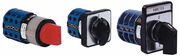
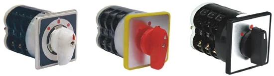
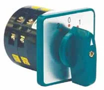
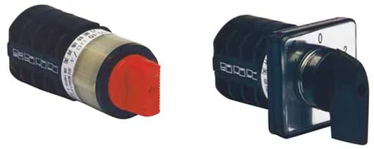
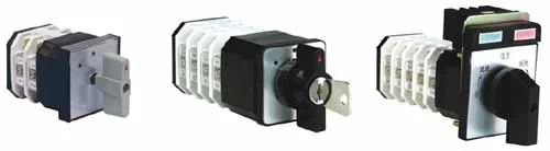
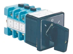
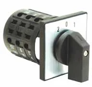
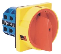
About the LW26 Rotary Switch
The LW26 Rotary Switch is part of the ELEHPD Rotary Switch range. Introduction LW26 series rotary switches are suitable for: on-off of an electrical circuit, change-over of electrical circuits, motor switch, instrument switch, and main switch. LW26 series rotary switches comply with: GB 14048.3, GB 14048.5, and IEC 60947-5-1. LW26 series rotary switches have six current ratings: 10A, 20A, 25A, 32A, 63A, 125A, and 160A. LW26-20 ELEHPD manufactures and exports low voltage electrical products from Yueqing, Zhejiang, China, supplying distributors, panel builders, M&E contractors and OEM buyers worldwide.
Typical applications
- Motor control centres and pump or fan starters
- Machine building, conveyors, packaging and CNC equipment
- HVAC control panels and building automation
- Water treatment, irrigation and pumping stations
- Panel retrofits replacing electromechanical control gear
How to specify the right Rotary Switch
- Size the contact rating for the inductive load, not just the resistive current (AC-3 duty for motors)
- Check the coil voltage and frequency available in the panel: 24 V DC, 110 V, 230 V or 400 V AC
- Confirm the auxiliary contact count needed for the control and indication circuit
- Match the enclosure rating to the environment (IP20 inside a panel, IP65 on the machine)
Specifications
|
Introduction
LW26 series rotary switches are suitable for: on-off of an electrical circuit, change-over of electrical circuits, motor switch, instrument switch, and main switch.
LW26 series rotary switches comply with: GB 14048.3, GB 14048.5, and IEC 60947-5-1.
LW26 series rotary switches have six current ratings: 10A, 20A, 25A, 32A, 63A, 125A, and 160A. LW26-20 and LW26-25 has the fingerproof terminals, which offered an extra advantage.
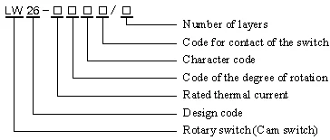
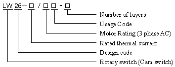
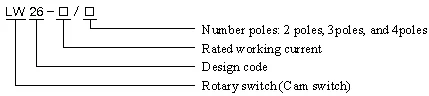
Designation
Use as control switches
![]()
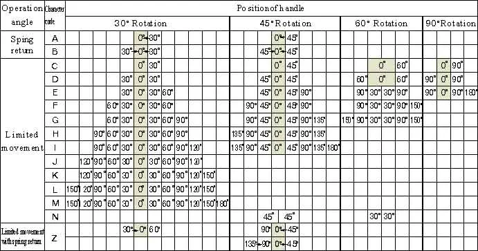
Re: Character code represent the rotating type, for instance, we have limited movement, spring return and limited movement with spring return.
Use as motor switch
![]()
Re: switches in this category normally rotate at 60°. And the SN normally rotate at 45°
Use as control switch for a main circuit
![]()
Re: switches in this category normally rotate at 60°
| Diagram for the operation and position of handle |
|
|
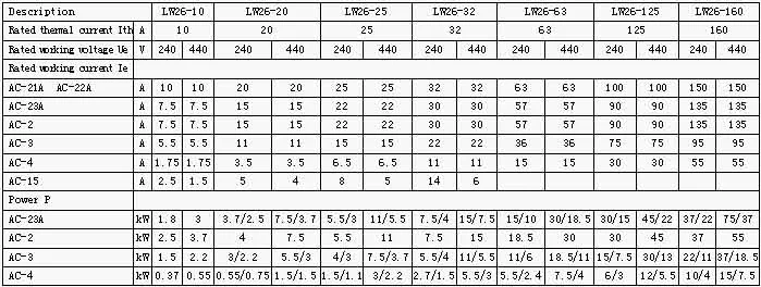
Technical parameters |
|
|
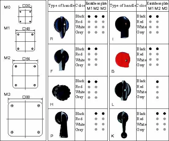
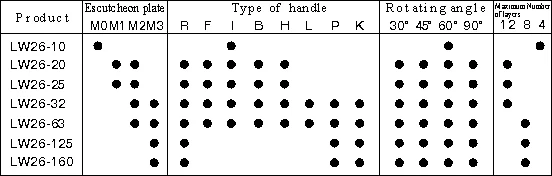
Escutcheon plate
![]()
Re:●Standard,●Optional.
Type of handle
![]()
Dimensions and installation
|
Description |
Escutcheon plate |
Dimensions (mm) |
Installation (mm) |
|
A |
B |
C |
L |
a |
b |
d1 |
d2 |
|
LW26-10 |
M0 square |
30 |
30 |
28 |
26.5+12n |
|
Φ8 |
Φ3.2 |
|
LW26-20 |
M1 square |
48 |
48 |
43 |
22+9.6n |
36 |
36 |
Φ8.5 |
Φ4.5 |
|
LW26-25 |
M1 square with rectangle plate added |
48 |
60 |
43 |
22+9.6n |
36 |
36 |
Φ8.5 |
Φ4.5 |
|
M2 square |
64 |
64 |
43 |
25+9.6n |
48 |
48 |
Φ10 |
Φ4.5 |
|
M2 square with rectangle plate added |
64 |
80 |
43 |
25+9.6n |
48 |
48 |
Φ10 |
Φ4.5 |
|
M1 square |
48 |
48 |
45.2 |
23+12.8n |
36 |
36 |
Φ8.5 |
Φ4.5 |
|
LW26-32 |
M1 square with rectangle plate added |
48 |
60 |
45.2 |
23+12.8n |
36 |
36 |
Φ8.5 |
Φ4.5 |
|
M2 square |
64 |
64 |
45.2 |
26.5+12.8n |
48 |
48 |
Φ10 |
Φ4.5 |
|
M2 square with rectangle plate added |
64 |
80 |
45.2 |
26.5+12.8n |
48 |
48 |
Φ10 |
Φ4.5 |
|
LW26-63 |
M2 square |
64 |
64 |
58 |
29.2+12.8n |
48 |
48 |
Φ10 |
Φ4.5 |
|
M2 square with rectangle plate added |
64 |
80 |
58 |
29.2+12.8n |
48 |
48 |
Φ10 |
Φ4.5 |
|
M2 square |
64 |
64 |
66 |
29.2+21.5n |
48 |
48 |
Φ10 |
Φ4.5 |
|
M2 square with rectangle plate added |
64 |
80 |
66 |
29.2+21.5n |
48 |
48 |
Φ10 |
Φ4.5 |
|
LW26-125 |
M3 square |
88 |
88 |
66 |
29.2+21.5n |
68 |
68 |
Φ10 |
Φ4.5 |
|
M3 square with rectangle plate added |
88 |
107 |
66 |
29.2+21.5n |
68 |
68 |
Φ10 |
Φ4.5 |
|
M3 square |
88 |
88 |
84 |
35+26.5n |
68 |
68 |
Φ13 |
Φ |
|
LW26-160 |
M3 square with rectangle plate added |
88 |
107 |
84 |
35+26.5n |
68 |
68 |
Φ13 |
Φ6 |
|
M3 square |
88 |
88 |
88 |
35+32.5n |
68 |
68 |
Φ13 |
Φ6 |
|
M3 square with rectangle plate added |
88 |
107 |
88 |
35+32.5n |
68 |
68 |
Φ13 |
Φ6 | Re: n for number of layers.
LW26-20 Round escutcheon plate
LW26-10 front installation、hole installation
| |
Frequently asked questions about the LW26 Rotary Switch
What is the difference between a contactor and a relay?
A contactor is built for switching power circuits repeatedly at high current, often with motor duty ratings (AC-3) and arc-suppressing chambers. A relay switches control signals at low current. In practice: contactor for the motor, relay in the control circuit that drives the contactor coil.
How do I calculate the correct contactor size for a motor?
Use the motor's full-load current, apply the AC-3 rating for the operating voltage, and allow for the number of starts per hour. As a rule of thumb, the contactor's AC-3 rating should be at least equal to the motor FLC, then step up one frame if the duty is heavy.
Do you supply the coil voltage I need?
Coil voltages are specified per order. Send the model number, coil voltage and frequency you require and we will confirm availability and lead time.
Are auxiliary contacts included?
Base models come with the standard auxiliary contact configuration for that frame. Add-on auxiliary blocks and mechanical interlocks can be quoted with the contactor.
Related Rotary Switch models
Further reading