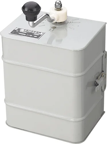
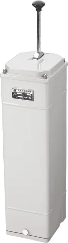
- machinery
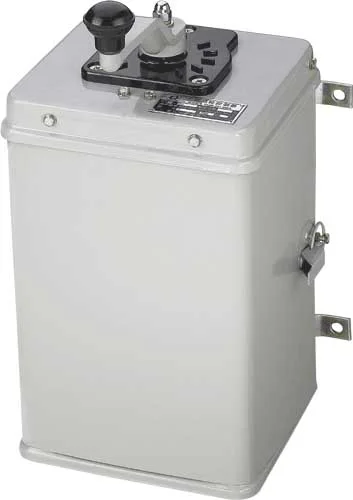
2.1 controllers outer coverings are the protected types.
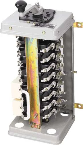
2.2 controllers contact systems for the double break point, the translation type, the extinguishing of arc system use the semi-enclosed type longitudinal seal pottery clay explosion chamber, and matches by the strong magnetism blows the electric circuit, extinguishing of arc ability.
2.3 contacts systems structure for the building block box type, the two-row arrangement, the assembly is convenient, the structure compact disassembles and assembles easily.
2.4 contacts closed and the separation relies on the bakelite cam piece composition different angle, with revolves the way realization.
- Technical performance and data
3.1Controller main engineering data
|
type |
voltage ratingV |
current ratingA |
Working position number |
The electric motor continues which when the circular telegram to lead
is 25% can control |
Fixed operating frequency/H |
The biggest working week bullies min |
avoirdupois(Kg) |
|
To front (rise) |
To after (drop) |
|
Rotor maximum current A |
Maximum work rate KW |
|
KT14-25J/1 |
380 |
25 |
5 |
5 |
32 |
11 |
600 |
10 |
14.5 |
|
KT14-25J/2 |
380 |
25 |
5 |
5 |
32 |
2×5.5 |
600 |
10 |
18.2 |
|
KT14-25J/3 |
380 |
25 |
1 |
1 |
32 |
5.5 |
600 |
10 |
13.5 |
|
KT14-60J/1 |
380 |
60 |
5 |
5 |
80 |
30 |
600 |
10 |
15 |
|
KT14-60J/2 |
380 |
60 |
5 |
5 |
80 |
2×11 |
600 |
10 |
18.2 |
|
KT14-60J/4 |
380 |
60 |
5 |
5 |
80 |
2×30 |
600 |
10 |
15 |
3.2 controllers mechanical lives in operating frequency 600/In h situation,Is not smaller than 150 104.
3.3 controllers operation strength are not bigger than 49N.
- overall dimension and installation dimension
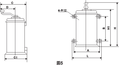
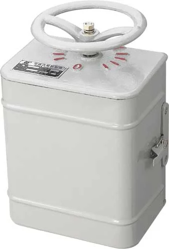
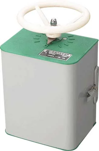
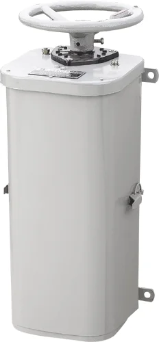
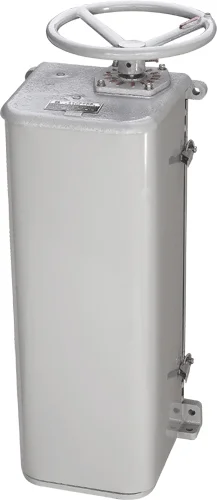
4.1 controllers contours like chart 5 shows:
4.2 controllers and install the size like table 2 to show: Shows 2mm
|
spec |
A |
B |
C |
C1 |
D |
H |
H1 |
L |
|
KT14-25J/1 |
270 |
270 |
305 |
248 |
175 |
510 |
405 |
300 |
|
KT14-25J/2 |
270 |
402 |
305 |
248 |
175 |
642 |
537 |
300 |
|
KT14-25J/3 |
270 |
270 |
305 |
248 |
175 |
510 |
405 |
300 |
|
KT14-60J/1 |
270 |
270 |
305 |
248 |
175 |
510 |
405 |
300 |
|
KT14-60J/2 |
270 |
402 |
305 |
248 |
175 |
642 |
537 |
300 |
|
KT14-60J/4 |
270 |
314 |
305 |
248 |
175 |
554 |
449 |
300 |
![]()
- wearing parts
Controller vulnerable see Table 3 tables 3
|
serial number |
|
Name |
Suitable situation |
|
1 |
5L×.551.002 |
Moving contact |
60J stator electric circuit contact and 60J/4 rotor electric circuit
|
|
2 |
5L×.551.001 |
Moving contact |
25J stator, rotor, auxiliary circuit contact and 60J/4 rotor electric
circuit auxiliary circuit contact and 60J/2 rotor electric circuit
contact |
|
3 |
5L×.551.005 |
Static contact |
60J stator electric circuit contact and 60J/1, 60J/4 rotor electric
circuit contact |
|
4 |
5L×.551.006 |
Static contact |
60J stator electric circuit contact and 60J/1, 60J/4 rotor electric
circuit contact |
|
5 |
5L×.551.004 |
Static contact |
25J stator, rotor, auxiliary circuit contact and 60J auxiliary circuit
contact and 60J/2 rotor electric circuit contact |
|
6 |
5L×.551.003 |
Static contact |
25J stator, rotor, auxiliary circuit contact and 60J auxiliary circuit
contact and 60J/2 rotor electric circuit contact |
|
7 |
8L×.282.003 |
Static contact |
25J and 60J contact system |
|
8 |
8L×.282.005 |
Reaction spring |
25J and 60J contact system |
|
9 |
8L×.744.002 |
Extinguishing of arc cover |
25J and 60J contact system |
- build in and servicing
6.1 installments precheck controller, like determination controller operation clever, when the files position is clear, the controller only then may install.
6.2 controllers must reliably fix on angle iron stand 'or' operation. Taiwan, outside meet the electric cable wire to be possible to penetrate by the foundation on hole.
6.3 controllers should reliably earth.
6.4 controllers stators electric circuit contact must install the complete extinguishing of arc cover.
6.5 with skids the friction in controller all rotations place, must the regular apply oil fat, by reduce the friction 6.6 controllers when work the contact but produces as a result of the electric arc burns black or the singeing phenomenon, this does not affect its performance, does not need to eliminate, otherwise counter-
can urge the controller to damage ahead of time.
6.7 controllers contacts exceeds the quota the travelling schedule to be smaller than when 0.5 millimeter should exchange the new contact, when installs the contact system and moves, the static contact
guidance place on its roller axis spreads the lubricating grease, and adjusts the double break point contact closed and the separation synchronism.
6.8 should eliminate in the controller regularly the dust.
6.9 pays attention to the fastening parts frequently whether has the loose situation, like has must eliminate.
- Ordering notice (when ordering must indicate)
(1)Ordering notice (when ordering must indicate)
(2)Easy to damage components chart or illustration number, name and quantity (silver contact basis special details consultation supply).
(3)General or is hot and damp.
- Electrical schematic diagram
![]()
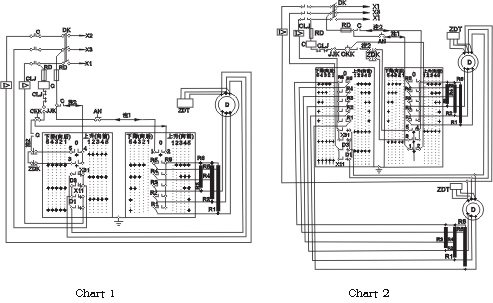
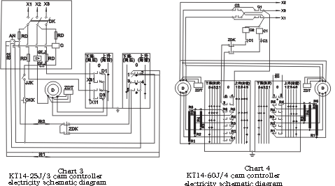
KT14-25J/1 KT14-25J/2
KT14-60J/1KT14-60J/1 cam controller electricity schematic diagram KT14-60J/2 cam controller electricity schematic diagram
gas
Note: 1st, in multi- direct motor drive system, other controllers note: 1st, in multi- direct motor drive system, other controllers contacts The contact 1 and 2 receives in this electric circuit. 1 and 2 receives in this electric circuit.
2nd, in multi- direct motor drive system, terminal switch and 2, in multi- motives actuation system, terminal switch and other controllers
Other controller contacts3 , 4 , 5 receive this electric circuit contact 3 4 5 to receive in this electric circuit.
In.
![]()
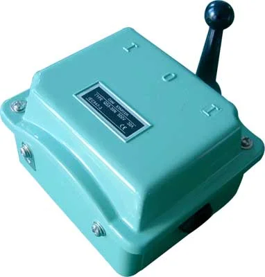
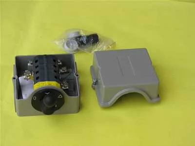
KT14-25J/1 KT14-25J/2
KT14-60J/1KT14-60J/1 cam controller electricity schematic diagram KT14-60J/2 cam controller electricity principle note: 1st, in multi- direct motor drive system, other notes: In multi- direct motor drive system, other controllers contacts. The controller contact 1 and 2 receives in this electric circuit in. 1 and 2 receives in this electric circuit.
2nd, in multi- direct motor drive system, terminal switch and Its controller contact 3 4 5 receives in this
electric circuit.