-
use
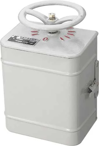
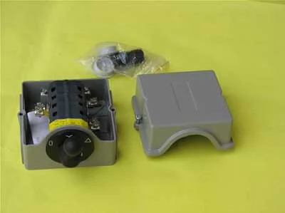
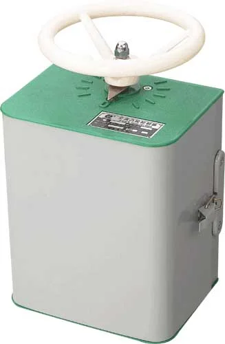
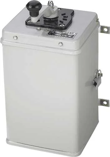
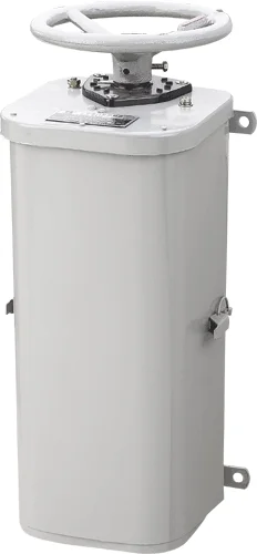
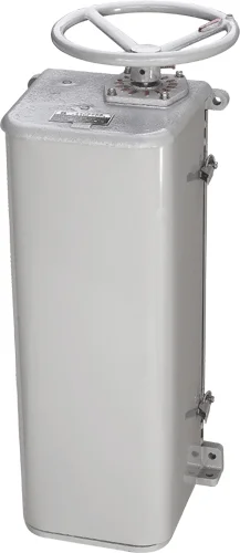
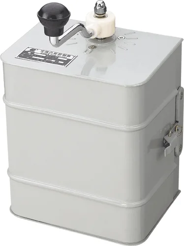
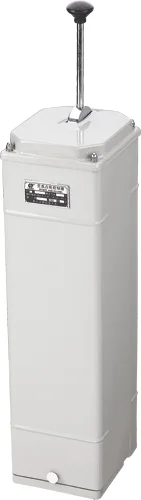
The KT10 series AC cam controller (hereafter refers to as
controller), mainly uses in AC 50HZ voltage to start, the
velocity modulation to 380 volts electric motors, and using of the
commutation, also is suitable for the similar request other electric
drive systems.
- sort、type and meanings
2.1 The KT10 series controller according to fixed gives off heat the electric current to divide 25A and the 60A two kinds
2.2 Model and meaning
![]()
- technical datasort
3.1The controller basic parameter see Table 1
|
TYPE |
Position number |
Rated current (A) |
Controller rated power (Kw) 380 V |
Operating force(N) |
Mechanical life(Million times ) |
The number of open & close times in one hour no more than |
|
left |
right |
|
KT10-60J/1 |
5 |
5 |
60 |
30 |
≯50 |
1.5 |
|
|
KT10-60J/2 |
5 |
5 |
60 |
① |
≯50 |
1.5 |
|
|
KT10-60J/3 |
1 |
1 |
60 |
16 |
≯50 |
1.5 |
|
|
KT10-60J/5 |
5 |
5 |
60 |
2×11 |
≯50 |
1.5 |
|
|
KT10-25J/1 |
5 |
5 |
25 |
11 |
≯50 |
1.5 |
|
|
KT10-25J/2 |
5 |
5 |
25 |
① |
≯50 |
1.5 |
|
|
KT10-25J/3 |
1 |
1 |
25 |
5 |
≯50 |
1.5 |
|
|
KT10-25J/5 |
5 |
5 |
25 |
2×5 |
≯50 |
1.5 |
|
|
KT10-60J/13F |
5 |
5 |
60 |
30 |
≯50 |
1.5 |
600③ |
|
KT10-60J/14F |
6 |
6 |
60 |
2×11 |
≯50 |
1.5 |
|
|
KT10-60J/15F |
6 |
6 |
60 |
① |
≯50 |
1.5 |
|
|
KT10-60J/24 |
4 |
4 |
60 |
16 |
≯50 |
1.5 |
|
|
KT10-25J/13F |
5 |
5 |
25 |
11 |
≯50 |
1.5 |
|
|
KT10-25J/14F |
6 |
6 |
25 |
2×5 |
≯50 |
1.5 |
|
|
KT10-25J/15F |
6 |
6 |
25 |
① |
|
|
|
|
KT10-25J/24 |
4 |
4 |
25 |
5 |
≯50 |
1.5 |
|
3.2Controller stator contact putting through breaks with the minute
3.2.1The control winds thread the type electrical machinery the controller
to see Table 2
|
Controller contact type |
The parameter of Put through & break |
Test time |
Test interval(S) |
Electrifie duration/time(ms) |
|
I/Ie |
U/Ue |
COSФ±0.05 |
Reversible transformation(time) |
onoff(time) |
switch on(time) |
|
Stator contact |
4 |
1.1 |
0.65 |
5 |
20 |
100 |
5~10 |
60~200 |
Note (1) I:Test current, (2) Ie:Rated heating current, (3) U: Testing voltage, (4) Ue: Rated working voltage.
3.2.2The control mouse cage type electrical machinery controller see Table
|
control |
The parameter of Put through & break |
Test time |
Oscilation frequencyf±10%(KHX) |
Crosses vibration coefficient r0.05 |
Experimental gap (S) |
Each time electrifies the time (ms) |
|
TYPE |
I/Ie |
U/Ue |
COSФ±0.05 |
Reversible transformation(hypo) |
Puts through the number of times(hypo) |
|
Puts through the minute to break |
|
|
|
KTJ10-25J/3 |
12 |
10 |
0.55 |
25 |
100 |
2000×10.2×Ue-0.8 |
1.1 |
5~10 |
6~200 |
|
KTJ10-60J/3 |
0.35 |
Note (1) I:Test current
(2) Ie:The control mouse cage type electrical machinery working voltage is 380 volt KT10-25J/3 controller fixed operating current is 10A.The control mouse cage type electrical machinery working voltage is 380 volt time KT10-60J/3 controller fixed operating current is 25A.
(3)U:Testing voltage。(4)Ue:Fixed working voltage.
3.3 The controller assists the contact putting through to break the ability with the minute to see Table 4.
-
|
Electric current category |
The contact fixed gives off heat the electric current |
Passes breaks the condition |
Experimental number of times(hypo) |
pitch time(S) |
Power On Hours(S) |
|
intercourse(A) |
voltage(V) |
COSФ±0.05 |
|
intercourse |
5 |
8.8 |
1.1×380 |
0.2 |
50 |
5~10 |
0.06~0.2 |
3.4 Controller stator electric circuit contact electricity life.
3.4.1The control winds thread the type electrical machinery the controller to see Table 5。
|
TYPE |
on-off time |
operating frequency(hypo/ hour) |
Power On Hours(S) |
Life number of times (ten thousand) |
|
electricity(A) |
voltage(V) |
COSФ±0.05 |
|
KT10 |
2.5le |
380 |
0.65 |
600 |
0.06~0.2 |
5 |
3.4.2The control mouse cage type electrical machinery controller sees table
|
PRODUCT TYPE |
Power On Hours |
Oscilation frequencyf±10%(KHZ) |
Crosses the vibration coefficient f±0.05 |
perating frequency(hypo/hour) |
Power On Hours(S) |
Life number of times (ten thousand) |
|
electricity(A) |
voltage(V) |
COSФ±0.05 |
|
KTJ10-25J/3 |
6le |
380 |
0.55 |
2000×10.2×Ue-0.8 |
1.1 |
600 |
0.06-0.2 |
5 |
|
KTJ10-60J/3 |
0.35 |
Note: (1) le: The control mouse cage type electrical machinery working voltage is 380 volt time KT10-25J/3 controller fixed operating current is 11A.
The control mouse cage type electrical machinery working voltage is 380 volt time KT10-60J/3 controller fixed operating current is 25A.
3.5The auxiliary contact electricity life parameter see Table 7
|
PRODUCT TYPE |
The rating gives off heat the electric current (A) |
on condition |
The minute breaks the condition |
Life number of times |
|
electricity(A) |
voltage(V) |
COSФ±0.05 |
electricity(A) |
voltage(V) |
COSФ±0.05 |
|
KT10 |
5 |
8 |
380 |
0.2 |
0.8 |
0.25 |
0.25 |
20万 |
3.6The controller control power, may refer to the limit to pass breaks the ability, the electricity life parameter designation。
- overall dimension and installation dimension
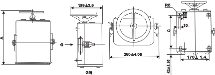
4.1 KT10-25J/1The controller contour and installs the size to see Figure 1。
![]()
Attempts the 1KT10-25J/1 controller outline drawing
|
TYPE |
KT10-25J/1 |
KT10-25J/2 |
KT10-25J/3 |
KT10-25J/5 |
|
A |
KT10-25J/13F |
KT10-25J/15F |
KT10-25J/24 |
KT10-25J/14F |
|
346±4.85 |
346±4.85 |
346±4.85 |
426±4.85 |
|
C |
206±3.6 |
222±3.6 |
206±3.6 |
286±4.05 |
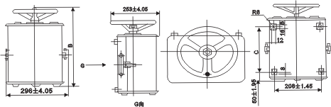
4.2KT10-60J/The controller contour and installs the size to see chart 2.
![]()
Chart 2 KT10-60J/Controller outline drawing
|
TYPE |
KT10-60J/1 |
KT10-60J/2 |
KT10-60J/3 |
KT10-60J/5 |
|
B |
KT10-60J/13F |
KT10-60J/15F |
KT10-60J/24 |
KT10-60J/14F |
|
422±4.85 |
422±4.85 |
422±4.85 |
522±5.5 |
|
C |
252±4.05 |
272±4.05 |
252±4.05 |
352±4.45 |
- Chart 2 KT10-60J/Controller outline drawing
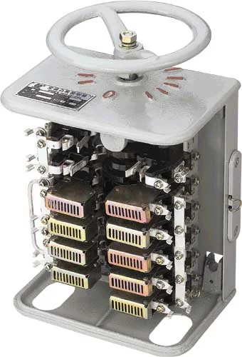
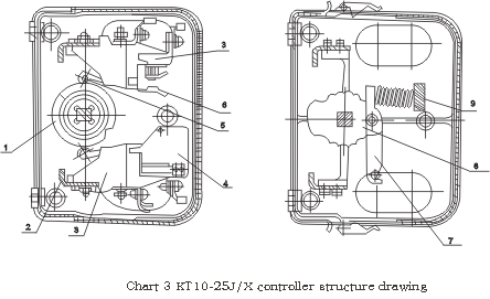
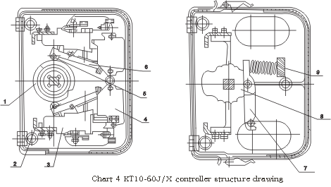
The controller structure see Figure 3 and chart 4 Is loaded with the cam shaft in the outer covering (1), the
prop (2) and fixes on the prop the contact system (3). The contact system makes the rotation type single break point, (6) on has the roller in the moving contact release lever (5); Has the inside lining pottery clay ferroguinous extinguishing of arc cover on the stator return route contact system; Has the ferroguinous extinguishing of arc on the partial rotors electric circuit contact system to cover (4). The controller localization is by locates the notch wheel (8), locates the release lever (7), the retaining spring (9) realizes. The controller makes the protected type, has the steel plate outer covering, about the base for cast irons the workpiece. When the cam shaft rotates, the contact system separates according to stipulation procedure Guan Hehe.
![]()
![]()
- Along with product supply engineering factor
a、Packing list;b、Product certificate;c、Product instruction booklet
![]()
![]()
![]()
![]()
- use and servicing
7.1The controller must reliably install on the wall or the bracket.
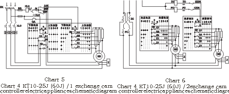
7.2When wiring must according to the controller electrical schematic
diagram wiring, all wires draw out by the base lower extremity two
wiring holes。
7.3In front of the circular telegram, must inspect the controller, the
electric motor, the resistor, the protection screen, the limit switch
and the brake magnet connection is whether correct, must inspect
earths whether reliably, then carries on the idling revolution. If the
controller changes to time the first grade of position, the electric
motor has not started to rotate, after then should stop supplying
power verifies the reason, only then continues to start. After the
electric motor from starts to revolve speed control to, the controller
only then changes to the next position, when transits from a position
to another position, the surge current should not surpass the relay
installation working current. Like wants to stop the electric motor,
should return the controller to the reference (nulling operation).
7.4The controller should the periodic inspection, each week not be
supposed to be short in, and must observe the following request.
7.4.1Should maintain in the friction spot has a thin layer the lubricant
(to be possible to use industry vaseline oil).
7.4.2The contact active face should not have the big melt spot, burns the
melt the spot to be possible to use the superfine file careful repair,
but does not allow the use sandpaper to repair and maintain.
7.4.3The contact active face should not have the big melt spot, burns the
melt the spot to be possible to use the superfine file careful repair,
but does not allow the use sandpaper to repair and maintain.
7.4.4Eliminates in the controller the dust and the soil, may use the
compressed air or do the cloth to wipe.
7.4.5Has damaged the components should promptly replace.