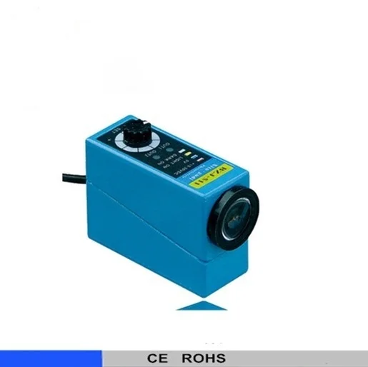
About the BZJ-511 Color mark sensor color sensor packing
The BZJ-511 Color mark sensor color sensor packing is part of the ELEHPD Color Mark Sensor range. COLOR MARK SENSOR PACKING SENSOR BZJ-511 Model and meaning: 1)Color mark sensor 2)Design program:1,2...... 3)Class to light path: 1. coaxial, 2. non coaxial 4)Class to light source: 1.single light source, 2. double light source 5)Color of light source: R: white, G: green 6)Class to logic: N-NPN, P-PNP ELEHPD manufactures and exports low voltage electrical products from Yueqing, Zhejiang, China, supplying distributors, panel builders, M&E contractors and OEM buyers worldwide.
Full catalogue description: BZJ-511 Color mark sensor color sensor packing sensor
Typical applications
- Motor control centres and pump or fan starters
- Machine building, conveyors, packaging and CNC equipment
- HVAC control panels and building automation
- Water treatment, irrigation and pumping stations
- Panel retrofits replacing electromechanical control gear
How to specify the right Color Mark Sensor
- Size the contact rating for the inductive load, not just the resistive current (AC-3 duty for motors)
- Check the coil voltage and frequency available in the panel: 24 V DC, 110 V, 230 V or 400 V AC
- Confirm the auxiliary contact count needed for the control and indication circuit
- Match the enclosure rating to the environment (IP20 inside a panel, IP65 on the machine)
Specifications
COLOR MARK SENSOR PACKING SENSOR BZJ-511
Model and meaning:
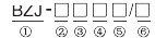
1)Color mark sensor
2)Design program:1,2......
3)Class to light path: 1. coaxial, 2. non coaxial
4)Class to light source: 1.single light source, 2. double light source
5)Color of light source: R: white, G: green
6)Class to logic: N-NPN, P-PNP
| 型号Model | BZJ-511 |
| 外形尺寸Size(mm) | 23*40*56mm |
| 工作电压Supply voltage | 10-30VDC |
| 使用环境温度Ambient temperature | 0℃~65℃ |
| 检测方式Detecting method | 同轴反射式Coaxial reflection |
| 设定距离Setting distance | 9mm±2mm |
| 光源色谱chromatogram of light | 红red、绿green、兰blue、白white |
| 光点Facula | 圆点Circular |
| 响应时间Response time | 200us/500us |
| 带载电流Current consumption | <200mA |
| 输出方式Output type | NPN |
| 外壳材料Material | 金属Metal |
| Protection | RP-power protection, Load short - circuit protection |
| WEIGHT | 200g |
| 引出线Cable | 2m |
BK: BLACK : switch signal output (NPN) WH: WHITE: analog signal output (PNP)
Notice: 1: Be sure to check the power supply is in line with the DC12 prior to power - 24 v + / - 10%, the highest do not exceed 40 v, otherwise may damage the color mark sensor. 2: To ensure high stability test, to ensure that be two things: one is the detection distance of rated offset, such as offset of 12 + 2 mm, when installation, must be that the offset is 12 mm, so that we can make the switch to have 4 mm up and down vibration stability region, and in the offset to 10 mm, the upper and lower vibration area is significantly reduced.;2 it is strictly according to the steps to adjust sensitivity. 3: When installation should prevent direct light into the optical lens or shading to take appropriate measures. 4: Working environment temperature, humidity, vibration, shock and other corrosive gases, are likely to affect the work of photoelectric switch, please pay attention to try to eliminate these effects. 5 : Pay attention to protect optical lens clean at ordinary times, avoid lens stand up when installation, to minimize dust.
|
Frequently asked questions about the BZJ-511 Color mark sensor color sensor packing
What is the difference between a contactor and a relay?
A contactor is built for switching power circuits repeatedly at high current, often with motor duty ratings (AC-3) and arc-suppressing chambers. A relay switches control signals at low current. In practice: contactor for the motor, relay in the control circuit that drives the contactor coil.
How do I calculate the correct contactor size for a motor?
Use the motor's full-load current, apply the AC-3 rating for the operating voltage, and allow for the number of starts per hour. As a rule of thumb, the contactor's AC-3 rating should be at least equal to the motor FLC, then step up one frame if the duty is heavy.
Do you supply the coil voltage I need?
Coil voltages are specified per order. Send the model number, coil voltage and frequency you require and we will confirm availability and lead time.
Are auxiliary contacts included?
Base models come with the standard auxiliary contact configuration for that frame. Add-on auxiliary blocks and mechanical interlocks can be quoted with the contactor.
Further reading